

|
|
||||
| Six-Beam Special Events Antenna | MBA6-9F-W-H3 To Be Discontinued |
|||

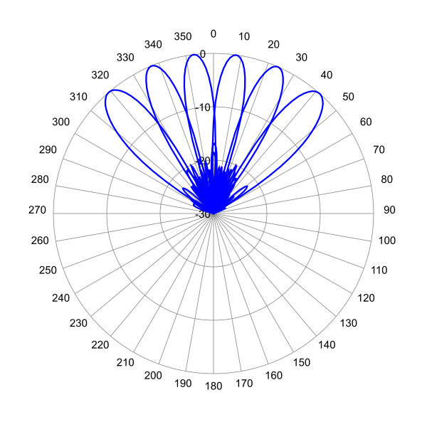
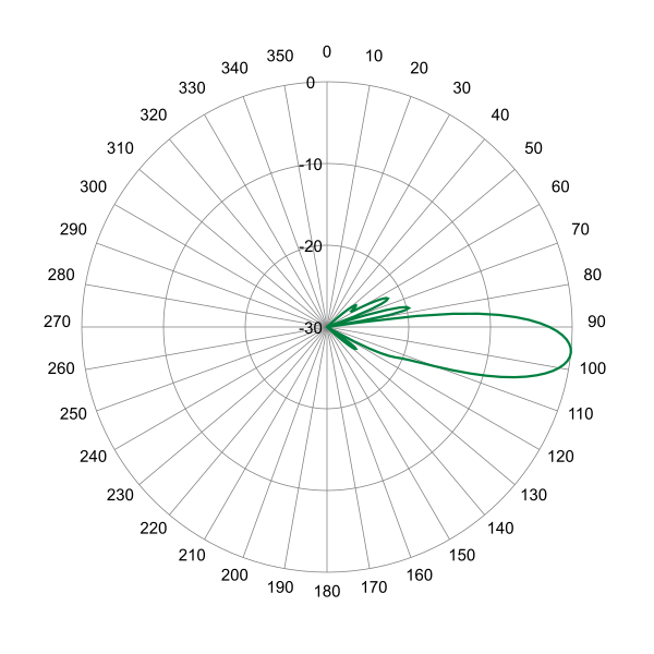
 Pattern Viewer
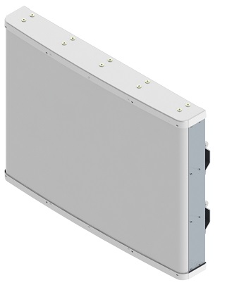 |
|
Mechanical
| Dimensions (L×W×D) | 30.5×45.9×6.6 in (775×1165×168 mm) |
| Survival Wind Speed | > 150 mph (> 241 kph) |
| Front Wind Load | 299 lbs (1328 N) @ 100 mph (161 kph) |
| Side Wind Load | 46 lbs (206 N) @ 100 mph (161 kph) |
| Equivalent Flat Plate Area | 11.7 ft2 (1.1 m2) |
| Weight * | 69.9 lbs (31.7 kg) |
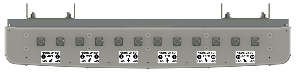
| Connector | 12 × 7-16 DIN female long neck |
| Mounting Pole | 2 x 2 to 5 in (5 to 12 cm) |
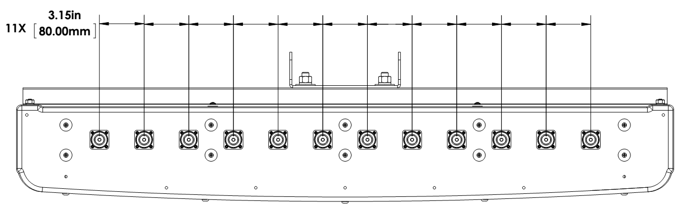
| Mounting Pole spacing | 31.5 in (800 mm) Center to Center |
| * Weight excludes mounting |
| Bottom View | |
 |
| Connector Spacing | |
 |


|
|


