|
|
||||
| Nine-Beam Special Events Antenna | MBMD9F-BW4A | |||

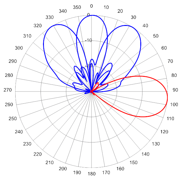
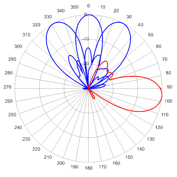
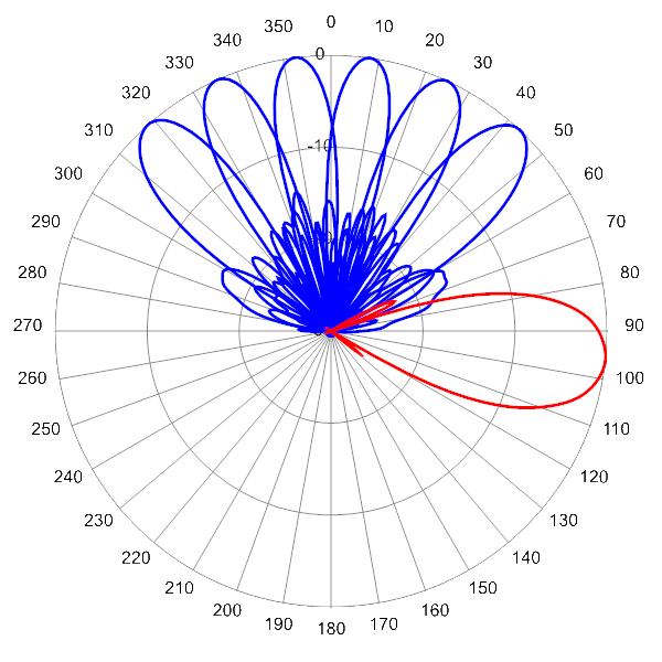
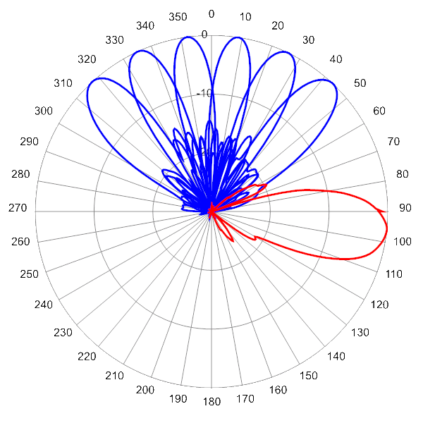
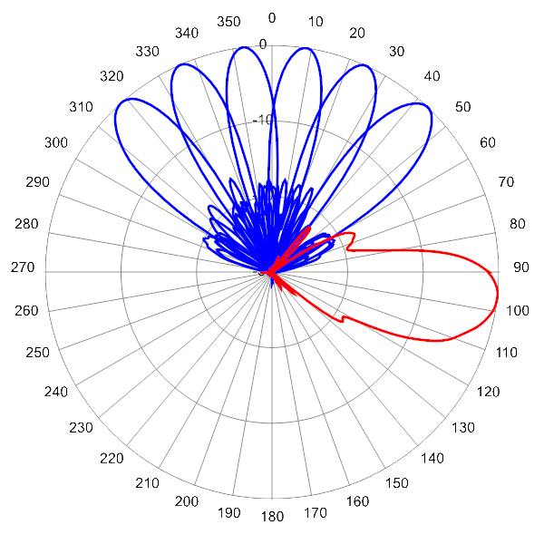
 Pattern Viewer
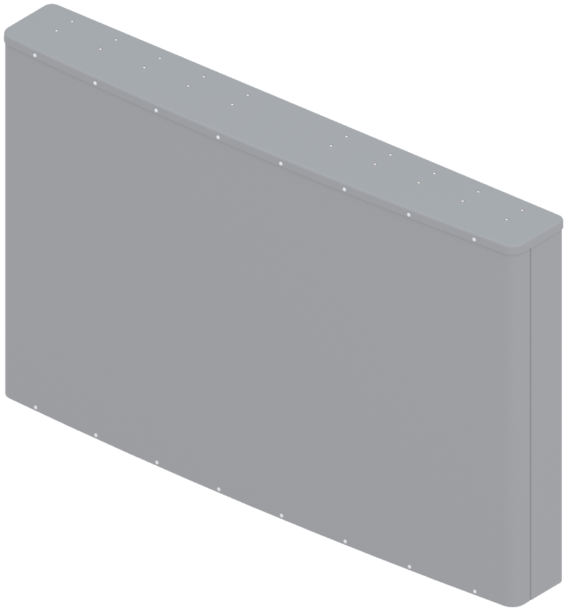 |
|
Mechanical
| Dimensions (L×W×D) | 48.3×77.6×10.4 in (1226×1970×265 mm) |
| Survival Wind Speed | > 150 mph (> 241 kph) |
| Front Wind Load1 | 780 lbf @ 100 mph 3471 N @ 161 kph |
| Side Wind Load1 | 15 lbf @ 100 mph 68 N @ 161 kph |
| Effective Projective Area (EPA), Front1 | 31 ft2 (3.0 m2) |
| Weight * | 176.4 lbs (80.0 kg) |
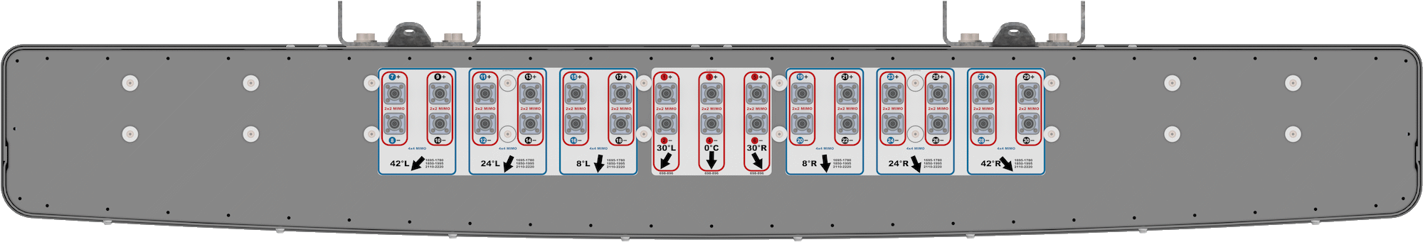
| Connector | 30 × 4.3-10 female |
| Mounting Pole | 2x 2 to 5 in (5 to 12 cm) |
| Mounting Pole Spacing | 33.1 in (841 mm) |
| 1Windload values calculated using CFD analysis * Weight excludes mounting |
|
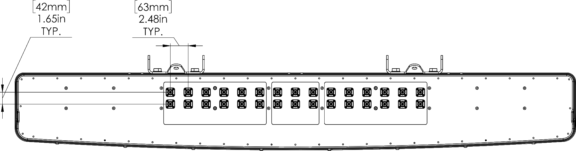
| Bottom View | |
 |
| Connector Spacing | |
 |
| MBK-02 | MBK-02 Mounting Kit |