| |
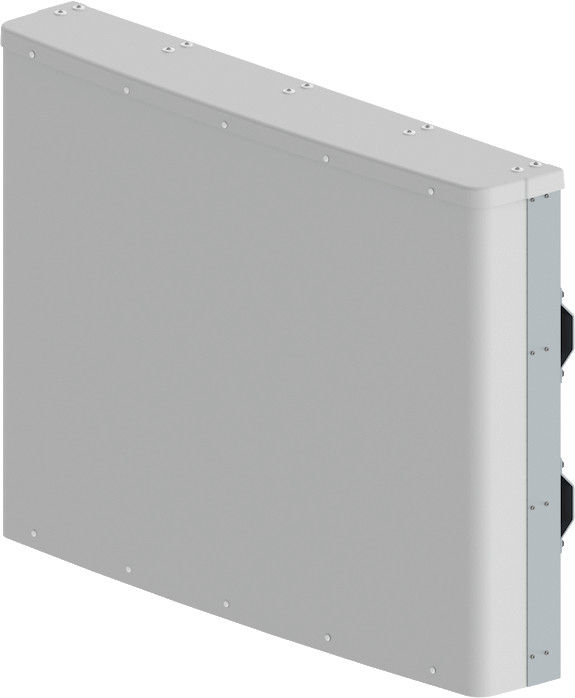
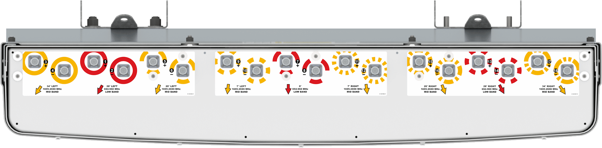
The CCI Six/Three Beam Special Events Antenna simultaneously supports (6) high-band and (3) low-band sectors from a single antenna. This Six/Three-Beam Antenna is intended for use at sporting and entertainment venues where social media and the ability to share photos and videos demand high capacity and high data rates. The high band ports provide coverage for DCS 1800 MHz, PCS 1900 MHz, AWS and AWS-3 1695/2180 MHz, UMTS 2100 MHz, WCS 2300 MHz and BRS 2600 MHz bands while the low band ports provide LTE 700 MHz, 800 MHz, Cellular 850 MHz and GSM 900 MHz band capability in a compact, 3.4 ft (1.0 m) high single enclosure. Each beam is fed by a pair of +45° and -45° cross-polarized ports. The high band beams are each roughly 15 degrees apart and each pair are evenly juxtaposed on the three low band beams. This antenna segments large audiences into multiple sectors thus enabling maximum spectrum re-use by sectorization, providing as much as nine times increase in network capacity. Our unique beam shaping technology provides fast roll off between beams, minimizing interference between sectors thus increasing the carrier to interference plus noise (CINR) ratio and lowering soft handover losses in LTE, UMTS/HSPA+ and CDMA/EVDO networks. Such an approach enhances data transfer rates within LTE, UMTS and EVDO network sectors and addresses “hotspots” in mobile wireless operator networks.
The single panel design of the CCI Six/Three-Beam Special Event Antenna offers the opportunity to reduce antenna count and directly replaces multiple narrow beam antennas. The antenna minimizes the need for optimization as each beam is spaced optimally for maximum throughput thus providing significant CAPEX and OPEX cost savings.
CCI antennas are designed and produced to ISO 9001 certification standards for reliability and quality in our state-of-the-art manufacturing facilities.
|


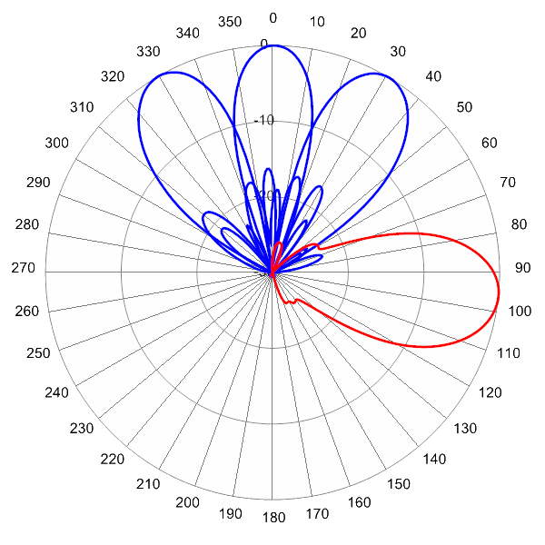
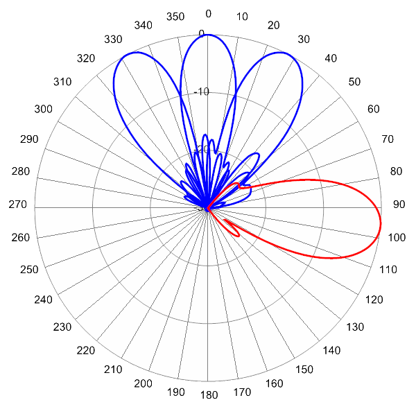
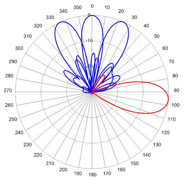
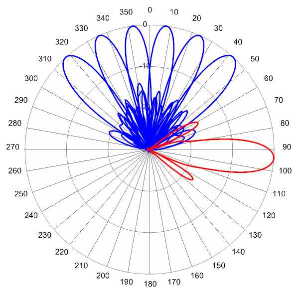
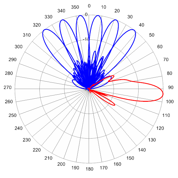
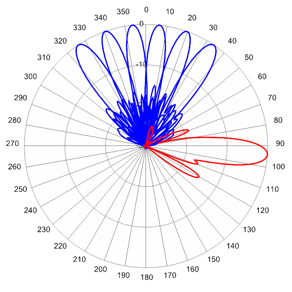
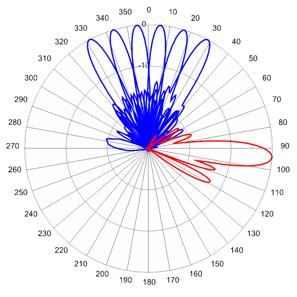
 Pattern Viewer