|
||||
Low Loss Combiner | LLC-1900-IN-10 | |||
|
Overview
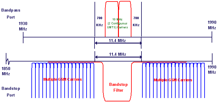
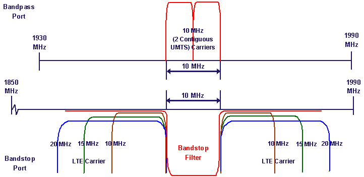
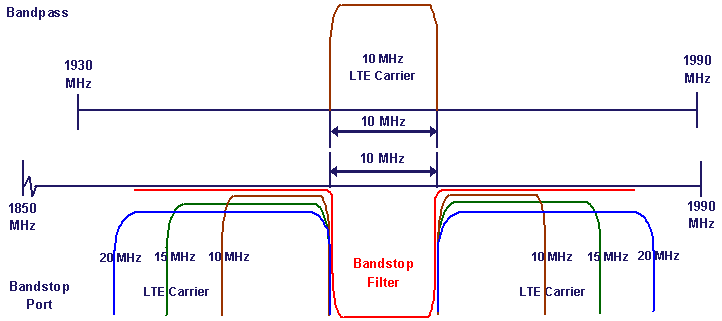
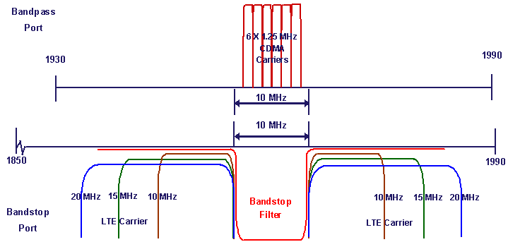
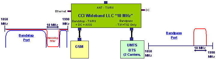
CCI’s PCS "0 MHz" Guard Band Low Loss Combiner (LLC) combines a 10 MHz band pass port with a synchronously tuned 10 MHz band stop port onto a single feeder without the insertion loss normally associated with passive combiners. The band pass port accomodates two (2) contiguous UMTS Carriers, one (1) 10 MHz LTE Carrier or up to six (6) contiguous NB-CDMA Cariers to be combined with either GSM, NB-CDMA, UMTS or LTE Carrier(s) on the band stop port. Utilizing precisely matched filters allows the placement of the Carrier(s) of the Bandpass (TX Only) to be positioned anywhere in the band while providing high rejection of unwanted spurious emissions and noise. The combining of LTE/LTE, UMTS/LTE & NB-CDMA/LTE, in most cases (LTE Carrier must be 10 MHz or wider), can be accomplished with zero (0) effective guard band, by leveraging the inherent guard bands of each technology (see Application Examples on Pages 3 thru 5). Additionally, the transmit paths are fully isolated to prevent intermodulation products. Once the combiner is tuned, no power is required, effectively becoming a pure passive low-loss filter combiner. Control (when powered) is via TCP/IP (Ethernet), requiring only a web browser to tune the Bandpass to the desired Center Frequency. All software is resident internally, no extra software or controller is required. |
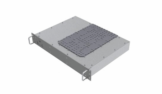
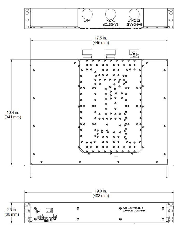
Electrical
RF Parameters | Ports | Frequency(MHz) | Specification |
Return Loss | Bandstop | 1850 - 1990 | 18 dB min. |
Bandpass | 1930 - 1990 | 18 dB min. | |
ANT | 1850 - 1990 | 18 dB min. | |
Insertion Loss | Bandstop to ANT | 1850 to (fc - 5) | 0.15 dB typ. |
(fc +5) to 1990 | 0.15 dB typ. | ||
Bandpass to ANT | (fc - 5) to (fc + 5) | 0.6 dB typ. | |
Isolation | Bandstop to Bandpass | 1930 to (fc -5) | 30 dB min., 35 dB typ. |
(fc - 5) to (fc + 5) | 25 dB min., 28 dB typ. | ||
(fc +5) to 1990 | 30 dB min., 35 dB typ. | ||
Tuning Range (Bandpass) | Any center frequency (fc) between 1935 - 1985 MHz, in 100 kHz steps | ||
Filter Range (Bandpass) | Any 10 MHz block starting at 1930 MHz up to and including any 10 MHz block ending at 1990 MHz |
General Characteristics | |
Impedance | 50 ohms |
Guard Band: | |
GSM/UMTS Combining | 700 kHz each side of Bandpass required |
UMTS/UMTS Combining | "0" Guard Band required |
UMTS/LTE Combining | "0" Guard Band required for 10 MHz or greater LTE carrier |
LTE/LTE Combining | "0" Guard Band required for 10 MHz or greater LTE carrier |
CDMA/LTE Combining | "0" Guard Band required for 10 MHz or greater LTE carrier (assumes six (6) contiguous, standard NB-CDMA Channels) |
Group Delay variation | 50 nS typ. |
Continuous Average Power | 500 W max. (all ports) |
Peak Envelope Power | 2 kW max. (all ports) |
IMD | <-110 dBm (-153 dBc) typical (2 × +43 dBm tones) all bands |
DC Pass Current/AISG Pass (Bandstop port to ANT port) |
3A/AISG signal (2.176 Mhz) per AISG 2.0 |
GSM/UMTS Combining: 700 kHz guard band required | |
UMTS/UMTS Combining: "0"guard band required |
UMTS/LTE Combining: "0"guard band required for 10 MHz or greater LTE carrier | |
LTE/LTE Combining: "0"guard band required for 10 MHz or greater LTE carrier |
CDMA/LTE Combining: "0"guard band required for 10 MHz or greater LTE carrier |
Mechanical
Connectors | 3 × 7-16 DIN female |
Data Connection | RJ45 Ethernet |
Alarm Connection | 6 pin Molex connector (4.2 mm) |
Power Connection | 2 pin Molex connector (4.2 mm) |
DC Power Requirement | 2A @ +24VDC (only required when tuning) |
DC Voltage | ±18 to ±76 VDC |
Dimensions (body only)(H×W×D) | 2.59 × 17.5 × 13.41 in. (65.79 × 444.5 × 340.61 mm) |
Dimensions (incl. connectors and handles)(H×W×D) | 2.59 × 19 × 15.3 in. (65.79 × 482.6 × 388.62 mm) |
Weight | 25.0 lbs (11.34 kg) |
Low Loss Combiner Outline Drawing |
Standards & Compliance
Safety | EN 60950-1, UL 60950-1 |
Emission | EN 55022 |
Immunity | EN 55024 |
Environmental | IEC 60068-2-1, IEC 60068-2-2, IEC 60068-2-5, IEC 60068-2-6, IEC-60068-2-11, IEC 60068-2-14, IEC 60068-2-18, IEC 60068-2-27, IEC 60068-2-29, IEC 60068-02-30, IEC 60068-2-52, IEC 60068-2-64, IEC61000-4-5, GR-63-CORE 4.3.1, EN 60529 IP67, IP68 |
|