|
|
||||
| TriBand Antenna | HPA65F-TE2A | |||

 Pattern Viewer
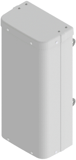 |
 |
|
Mechanical
| Dimensions (L×W×D) | 25.5×11.9×7.6 in (647×303×193 mm) |
| Survival Wind Speed | > 150 mph (> 241 kph) |
| Front Wind Load | 65 lbs (288 N) @ 100 mph (161 kph) |
| Side Wind Load | 43 lbs (190 N) @ 100 mph (161 kph) |
| Equivalent Flat Plate Area | 2.5 ft2 (0.2 m2) |
| Weight* | 14.3 lbs (6.5 kg) |
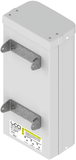
| Connector | 6× 4.3-10 female |
| Mounting Pole | 2 to 5 in (5 to 12 cm) |
| * Weight excludes mounting |
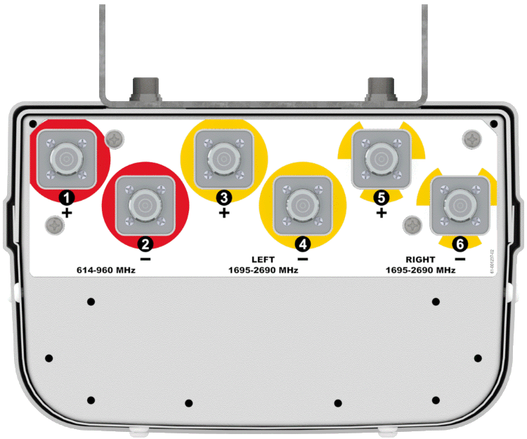
| Bottom View | HPA65F-TE2AA |
 |
| Connection Spacing Diagram | HPA65F-TE2AA |
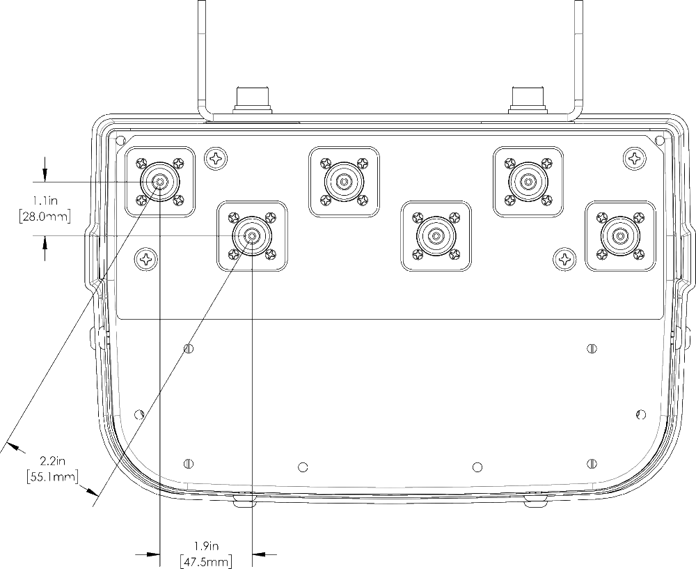 |
| Antenna Array Configuration | HPA65F-TE2AA |
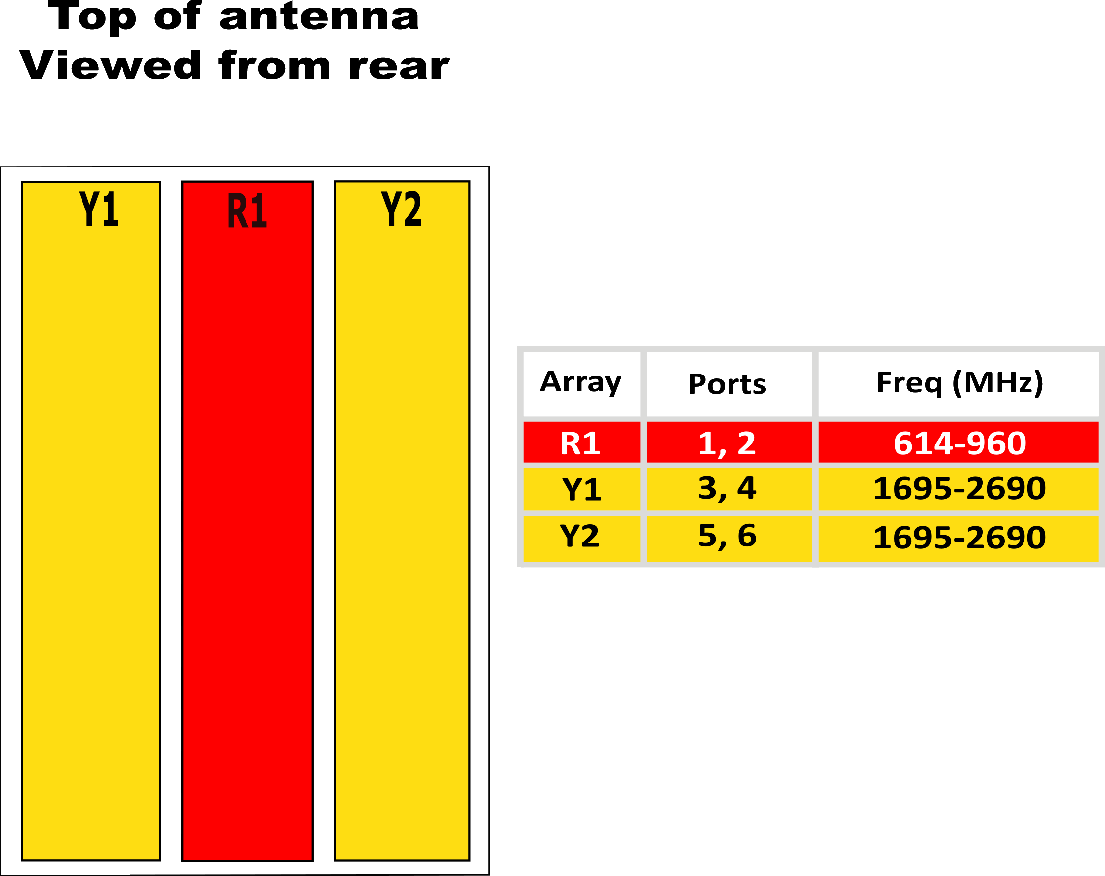 |
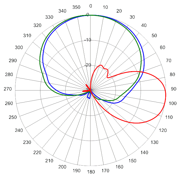
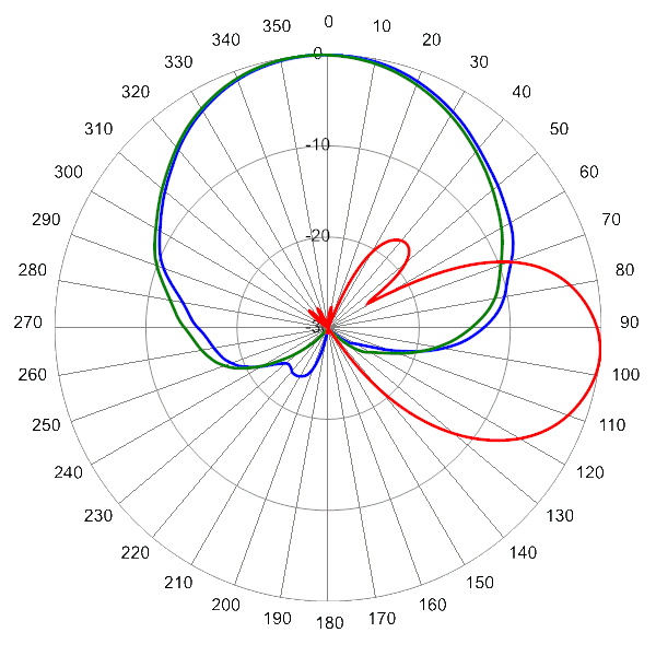
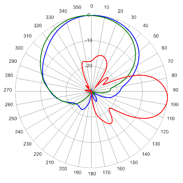
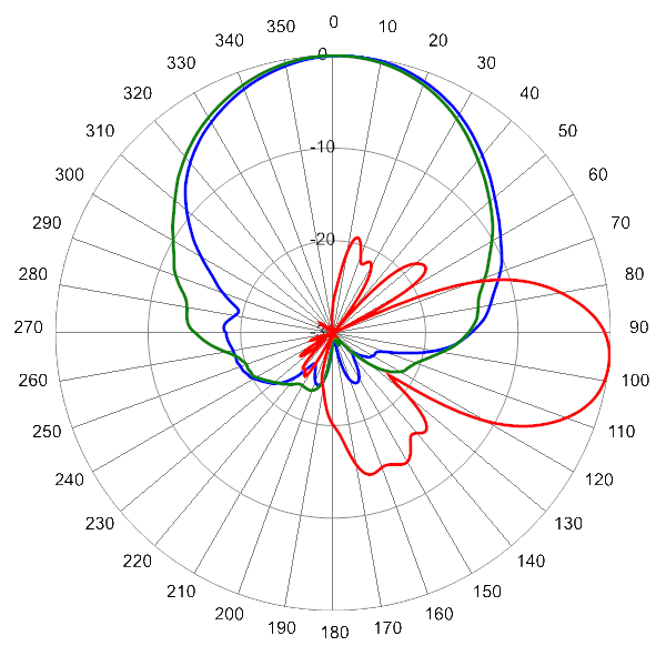
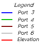
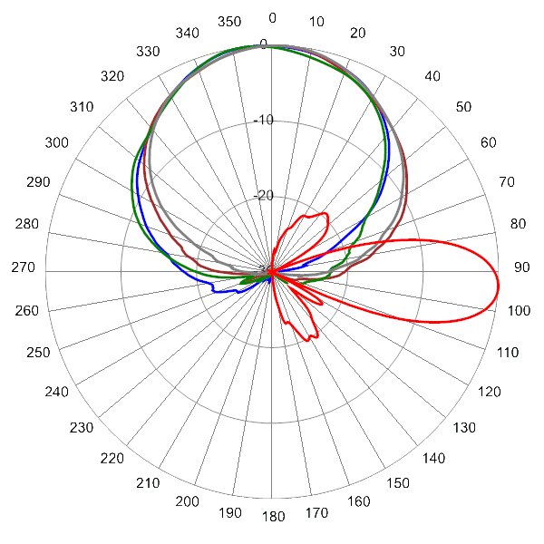
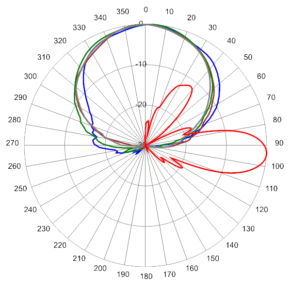
Typical Antenna Patterns
| For detailed information on additional antenna patterns, contact customer support at | ||
 |
 |
 |
| 614 MHz Azimuth with Elevation 6° | 704 MHz Azimuth with Elevation 6° | |
|
 |
 |
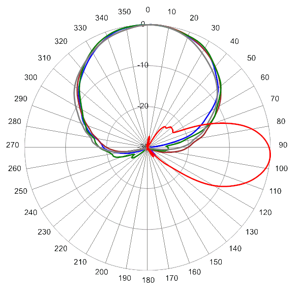
| 824 MHz Azimuth with Elevation 6° | 945 MHz Azimuth with Elevation 6° |
 |
 |
 |
| 1710 MHz Azimuth with Elevation 4° | 1970 MHz Azimuth with Elevation 4° | |
|
 |
 |
| 2155 MHz Azimuth with Elevation 4° | 2500 MHz Azimuth with Elevation 4° |
| MBK-03 | MBK-03 Mounting Kit |