|
||||
AWS/PCS Dual Band TMA with Bypass | TSB-1921-xxx | |||
|
Overview
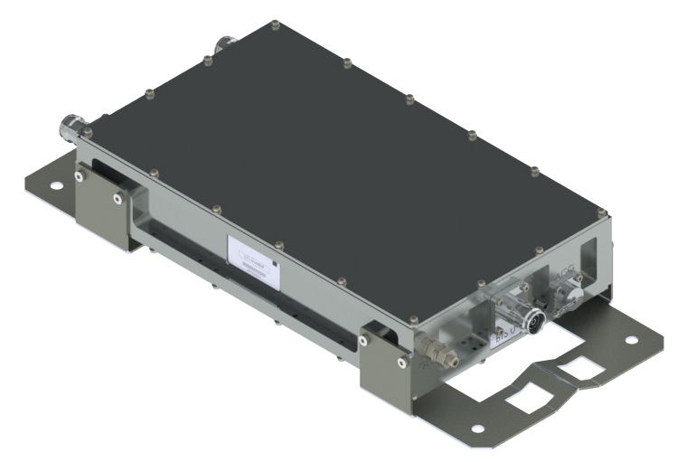
CCI’s Dual Band TMA (AWS/PCS), includes AWS-3 and 600/700/850 bypass is available in a single or twin configuration. Each TMA is fully duplexed and shares a single LNA for both bands. The bypass path provides excellent isolation to the TMA path. Separate antenna ports for the bypass and TMA paths are combined onto a single BTS port. The TMA's low noise, highly linear amplifiers improve the uplink sensitivity and the receive performance of the base station. The TMA is configurable to operate using either CWA or AISG 2.0 communication protocols. The TMA supports CDMA, EDGE/GSM, UMTS and LTE BTS equipment. The unit is ideally suited for sites upgraded to dual-band using the existing infrastructure. The TMA allows the sharing of feeder lines for all bands thus reducing tower loading, leasing, and installation costs. Input and output connectors are located inline for ease of installation in space constrained areas such as uni-pole structures and stealth antennas. Technical Description: 
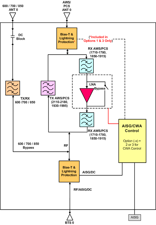
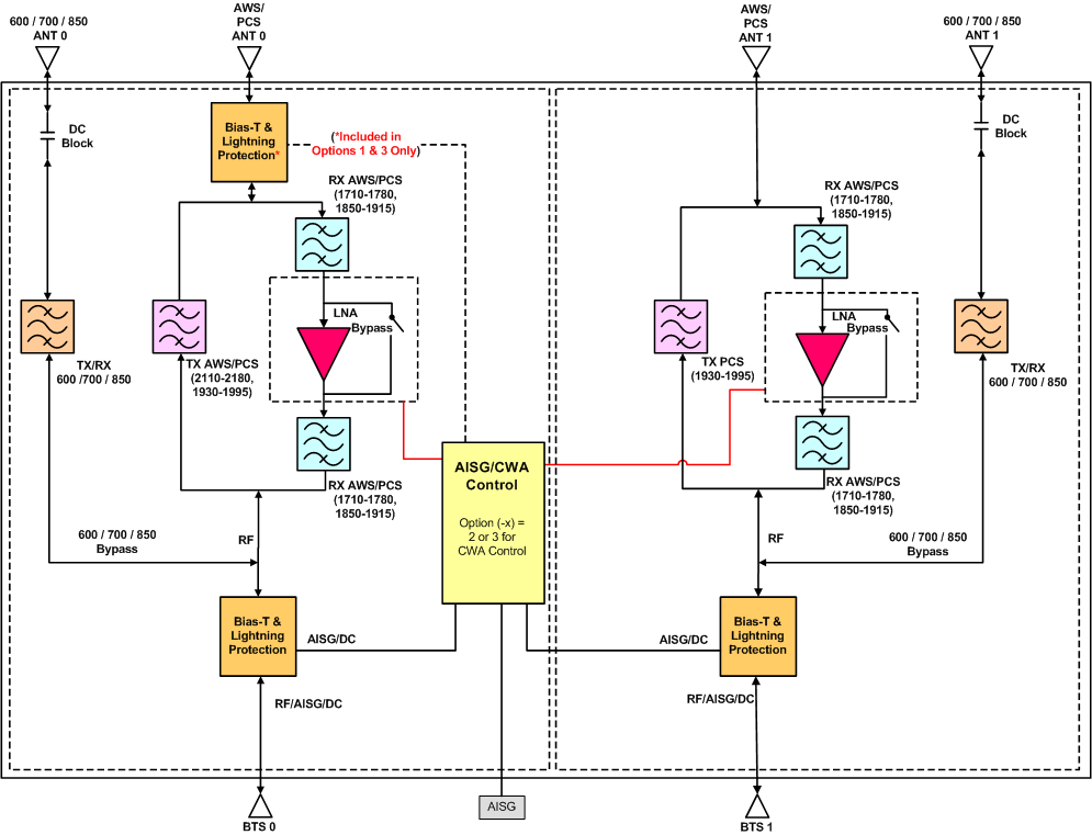
The TMA system is an outdoor dual band tower mount unit which provides low noise amplification of PCS and AWS uplink signals combined with 600/700/850 bypassed signals from separate antenna ports to a common BTS port. Each unit consists of multiple band-pass filters, one low noise amplifier (LNA) with bypass failure circuitry, one bias tee, AISG control circuitry, and lightning protection circuitry all housed in an IP67 enclosure suited to long life masthead mounting. The AWS and PCS paths are dual duplexed to separate the low power uplink signals from the high power down link signals at the BTS and antenna ports. The AWS and PCS uplink signals are amplified with a dedicated ultra-low noise PHEMT LNA with adjustable gain control. The unit provides protection against lightning strikes via a multistage surge protection circuit. DC power and AISG 2.0 control are provided via the BTS feeder cable. The unit is capable of switching between AISG and CWA modes as follows. On power up, the unit restores the previous mode at power down. The unit will switch from AISG to CWA mode by applying DC to both BTS ports. The unit will switch from CWA to AISG mode when it detects an AISG message on either BTS port. The unit can also be locked to a specific mode by entering keywords in specific device data fields as outlined. In CWA mode, the unit requires 12VDC at each BTS port and follows typical current window convention (see specifications in "General Characteristics"). In AISG mode, the unit will accept 10-30 VDC from either BTS port. In AISG mode, the unit does not require an AISG 2.0 compatible site control unit (SCU) and may also be powered by a standard power distribution unit (PDU). This TMA can be configured with either 7-16 or 4.3-10 connectors and also has the option of providing DC/AISG pass through to the antenna. |
Electrical
RF Parameters | Ports | Frequency(MHz) | Specification |
Return Loss | ANT | 1710 - 1780 | 18 dB min. (15 dB bypass mode) |
2110 - 2180 | 18 dB min. | ||
1850 - 1915 | 18 dB min. (15 dB bypass mode) | ||
1930 - 1995 | 18 dB min. | ||
600/700/850 | 555 - 960 | 18 dB min. | |
BTS | 1710 - 1780 | 18 dB min. (15 dB bypass mode) | |
2110 - 2180 | 18 dB min. | ||
1850 - 1915 | 18 dB min. (15 dB bypass mode) | ||
1930 - 1995 | 18 dB min. | ||
555 - 960 | 18 dB min. | ||
Gain | ANT - BTS | 1710 - 1780 | 7 to 13 dB adjustable in 0.25 dB steps via AISG (± 1.0 dB) See Note 1 |
1850 - 1910 | 6 to 12 dB adjustable in 0.25 dB steps via AISG (± 1.0 dB) | ||
1910 - 1915 | 5 to 11 dB adjustable in 0.25 dB steps via AISG (± 1.0 dB) See Note 2 | ||
Insertion Loss | ANT - BTS (RX Bypass mode) | 1710 - 1780 | 1.4 typ. dB @25°C, 1.6 dB @65°C (± 0.1 dB) |
1850 - 1910 | 1.8 typ. dB @25°C, 2.0 dB @65°C (± 0.5 dB) | ||
1910 - 1915 | 2.5 typ. dB @25°C, 3.1 dB @65°C (± 0.5 dB) | ||
BTS - ANT | 2110 - 2180 | 0.2 dB typ. (± 0.05 dB) | |
1930 - 1995 | 0.3 dB typ., 0.75 dB max | ||
600/700/850 - BTS | 555 - 960 | 0.1 dB typ. | |
Isolation | 600/700/850 - ANT | 555 - 960 | 80 dB min. |
1710 - 2180 | 50 dB min. | ||
Noise Figure | ANT - BTS | 1710 - 1780 | 1.2 dB typ. @ 25°C, 1.4 dB @ 65°C |
1850 - 1910 | 1.3 dB typ. @ 25°C, 1.5 dB @ 65°C | ||
1910 - 1915 | 1.7 dB typ. @ 25°C, 1.9 dB @ 65°C | ||
Input Third Order Intercept Point | ANT - BTS | 1710 - 1780 | +12 dBm min. at max. gain |
1850 - 1915 | +12 dBm min. at max. gain | ||
Note 1: The gain at 1710-1780 will be 1 dB higher than the set gain. | |||
Note 2: The gain at 1910-1915 will be 1 dB lower than the set gain. |
General Characteristics | |
Impedance | 50 ohms |
Continuous Average Power | 200 W max. |
Peak Envelope Power | 2 kW max. |
Intermodulation Performance(all ports) | <-117 dBm (-160 dBc) typical (2 × +43 dBm tones) all bands |
Operating Voltage (AISG Mode) | +10 VDC to +30 VDC provided via coax |
Operating Voltage (CWA Mode) | +10 VDC to +18 VDC, +12 VDC Nominal provided via coax |
AISG 2.0 Mode Single Power Consumption | < 2.0 W |
AISG 2.0 Mode Twin Power Consumption | < 3.0 W |
CWA Mode Current Consumption - Normal | < 140 mA per TMA |
CWA Mode Current Consumption - Alarm | > 200 mA per TMA |
Mechanical
Model | Single | Twin |
Connectors | 3 × 7-16 DIN female or 3 × 4.3-10 female |
6 × 7-16 DIN female or 6 × 4.3-10 female |
Dimensions w/Bracket | 8.07 × 18.07 × 3.19 in. (205.0 × 459.0 × 81.0 mm) |
8.07 × 18.07 × 5.51 in. (205.0 × 459.0 × 140.0 mm) |
Housing Dimensions | 7.68 × 13.03 × 2.68 in. (195.0 × 331.0 × 68.0 mm) |
7.68 × 13.03 × 5.0 in. (195.0 × 331.0 × 127.0 mm) |
Weight | 16.0 lbs (7.3 kg) | 29.0 lbs (13.2 kg) |
Frontal Wind Load | 304.1 N @150km/hour | 304.1 N @150km/hour |
Lateral Wind Load | 76.5 N @150km/hour | 143.0 N @150km/hour |
PCS/AWS Single TMA with 600/700/850 band bypass Outline Drawing |
PCS/AWS Twin TMA with 600/700/850 band bypass Outline Drawing |
Accessories
SCU-AISG2-3 | AISG 2.0 Site Controller |
RET-CBK | AISG Cable Kit |
BT-0821-DMDF-AG-O | DIN-Male RF Port, DIN-Female RF+DC+AISG Port |
BT-0821-DFDM-AG-O | DIN-Female RF Port, DIN-Male RF+DC+AISG Port |
BT-0821-DFDF-AG-O | DIN-Female RF Port, DIN-Female RF+DC+AISG Port |
Product Information
TSB-1921-x-S2 Dimension Drawing | ||
TSB-1921-x-T2 Dimension Drawing |
Parts & Accessories
TSB-1921-xS1 | AWS/PCS Single TMA with bypass and 7-16 connectors |
TSB-1921-xS2 | AWS/PCS Single TMA with bypass and 4.3-10 connectors |
TSB-1921-xT1 | AWS/PCS Twin TMA with bypass and 7-16 connectors |
TSB-1921-xT2 | AWS/PCS Twin TMA with bypass and 4.3-10 connectors |
Option (-x) | Description |
0 | AISG/CWA control with no AISG pass through antenna port |
1 | AISG/CWA control with AISG pass through antenna port |
2 | AISG control with no AISG pass through antenna port |
3 | AISG control with AISG pass through antenna port |
Standards & Compliance
Safety | EN 60950-1, UL 60950-1 |
Emission | EN 55022 |
Immunity | EN 55024 |
Environmental | IEC 60068-2-1, IEC 60068-2-2, IEC 60068-2-5, IEC 60068-2-6, IEC-60068-2-11, IEC 60068-2-14, IEC 60068-2-18, IEC 60068-2-27, IEC 60068-2-29, IEC 60068-02-30, IEC 60068-2-52, IEC 60068-2-64, IEC61000-4-5, GR-63-CORE 4.3.1, EN 60529 IP68 |
|