|
|
||||
| Quad Port High-Band Antenna | QPA33F-H2A | |||

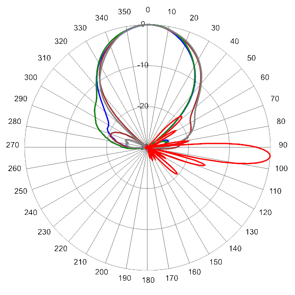
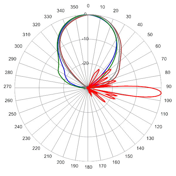
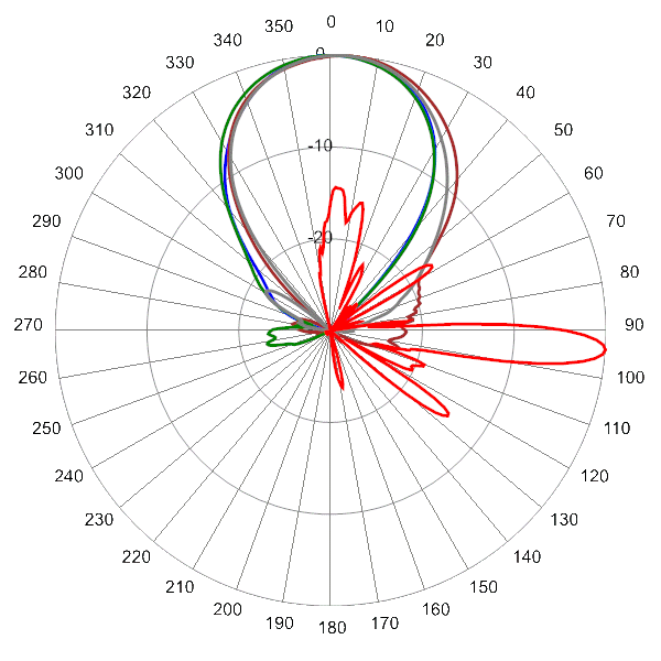
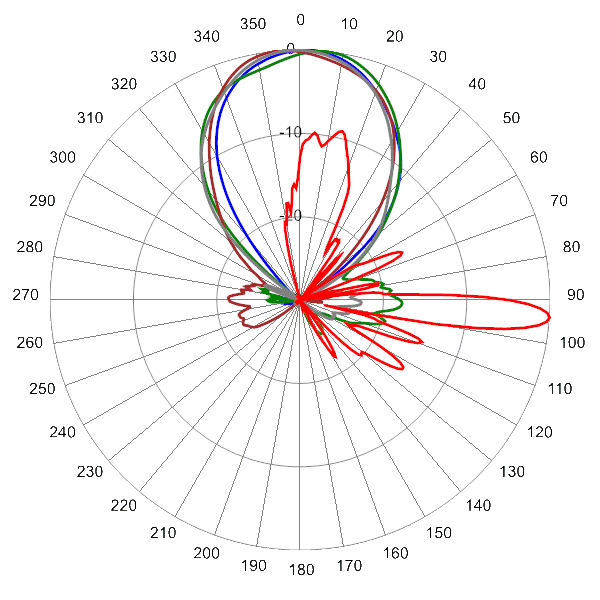
 Pattern Viewer
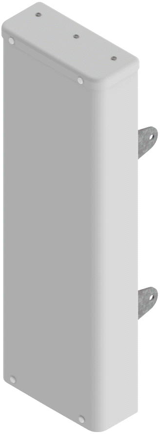 |
 |
|
Mechanical
| Dimensions (L×W×D) | 28.6×9.4×4.0 in (727×238×102 mm) |
| Survival Wind Speed | > 150 mph (> 241 kph) |
| Front Wind Load | 58 lbs (260 N) @ 100 mph (161 kph) |
| Side Wind Load | 29 lbs (128 N) @ 100 mph (161 kph) |
| Equivalent Flat Plate Area | 2.3 ft2 (0.2 m2) |
| Weight * | 11.9 lbs (5.4 kg) |
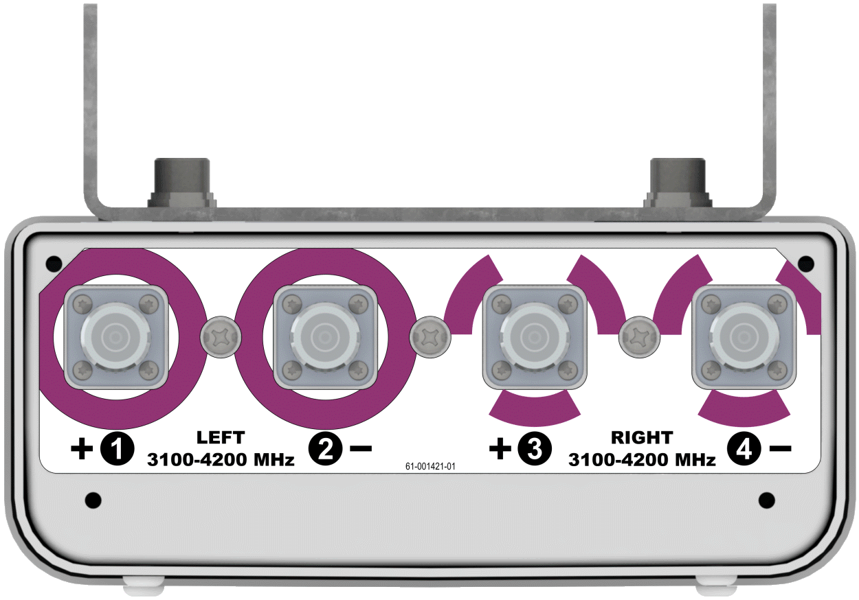
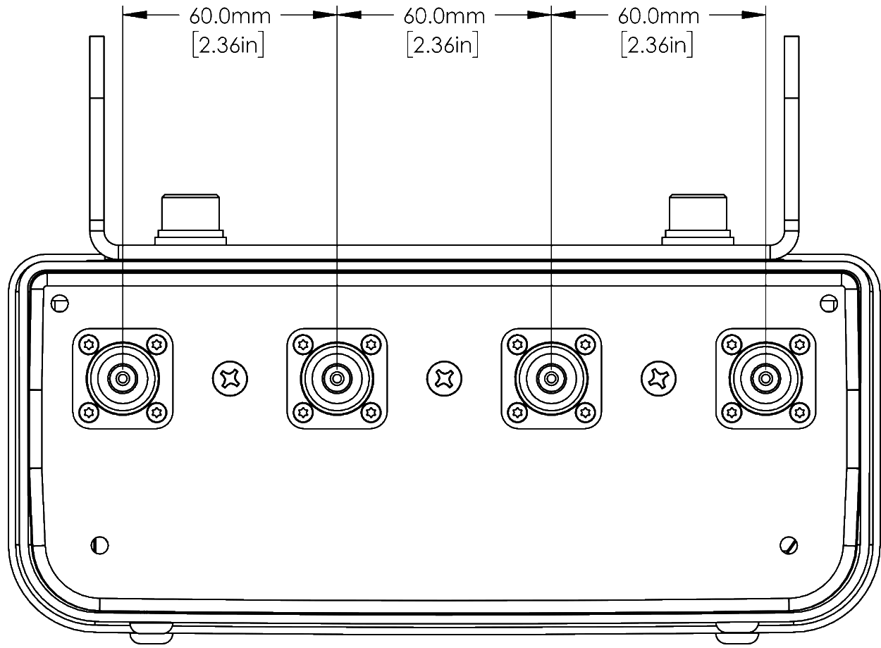
| Connector | 4 × 4.3-10 female |
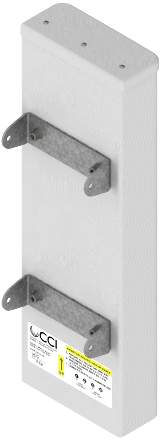
| Mounting Pole | 2 to 5 in (5 to 12 cm) |
| * Weight excludes mounting |
| Bottom View | QPA33F-H2A |
 |
| Connector Spacing Diagram | QPA33F-H2A |
 |

| MBK-03 | MBK-03 Mounting Kit with 0° - 10° mechanical tilt |